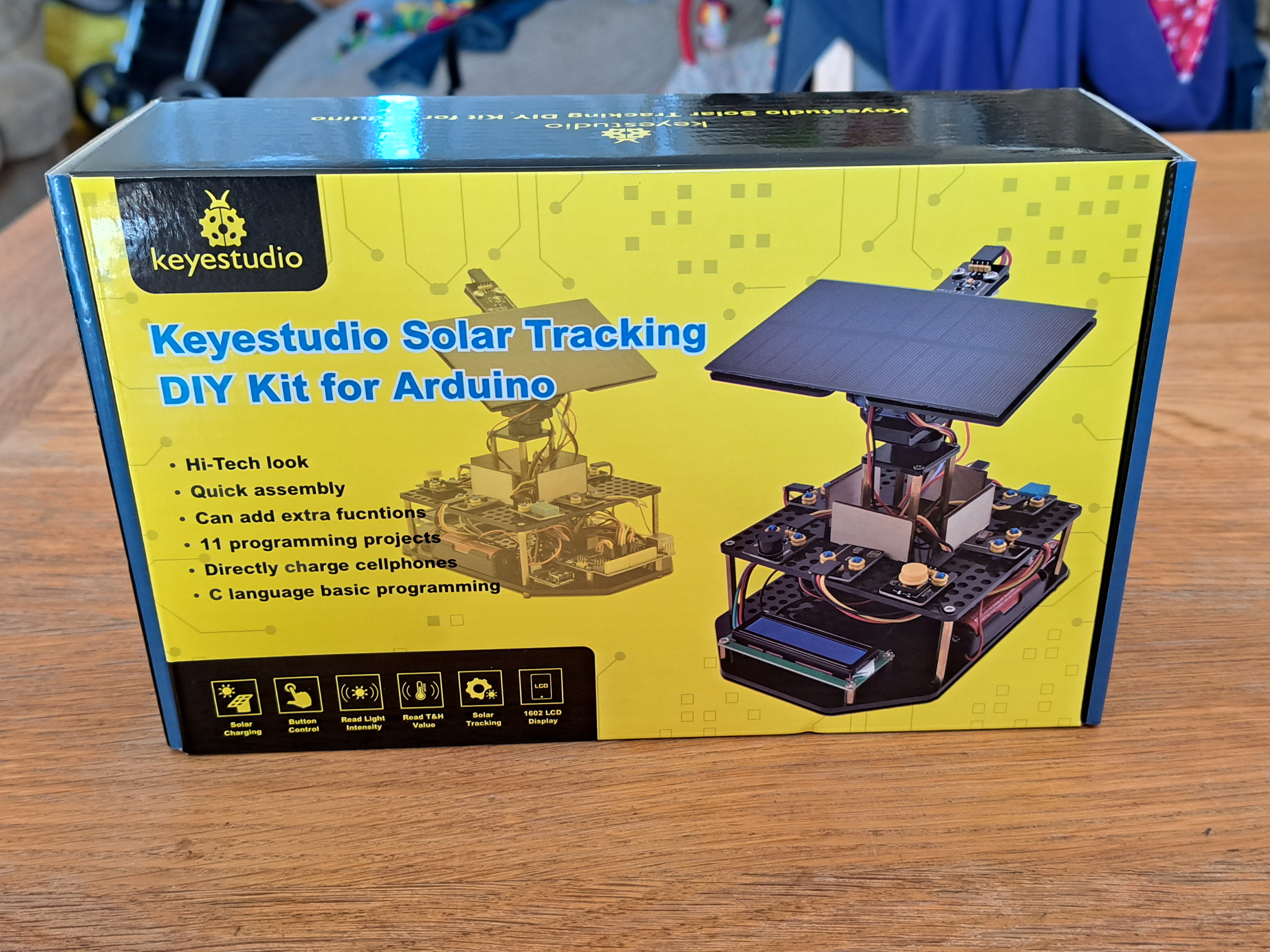
Review of Keyestudio's Solar Tracking Kit
By Dr Jennifer Martay PE, Course Leader for Medical Engineering at Anglia Ruskin University
I am a Biomedical Engineer, interested in all things engineering. This kit gave me the chance to learn more about electronics as well as solar power.
I was really pleased with the Keyestudio Smart House I built recently so was excited about this kit!
What did I think about it? The kit is mostly straight-forward, if maybe a bit fiddly, to build. The Arduino code is error-free, and the solar panel
successfully follows a moving light source. For more details, watch the video below and/or keep reading!
First Impressions
The kit contains everything you need to build the solar tracking device, complete with magnetic screwdrivers and online instruction manual and Arduino set-up information and codes.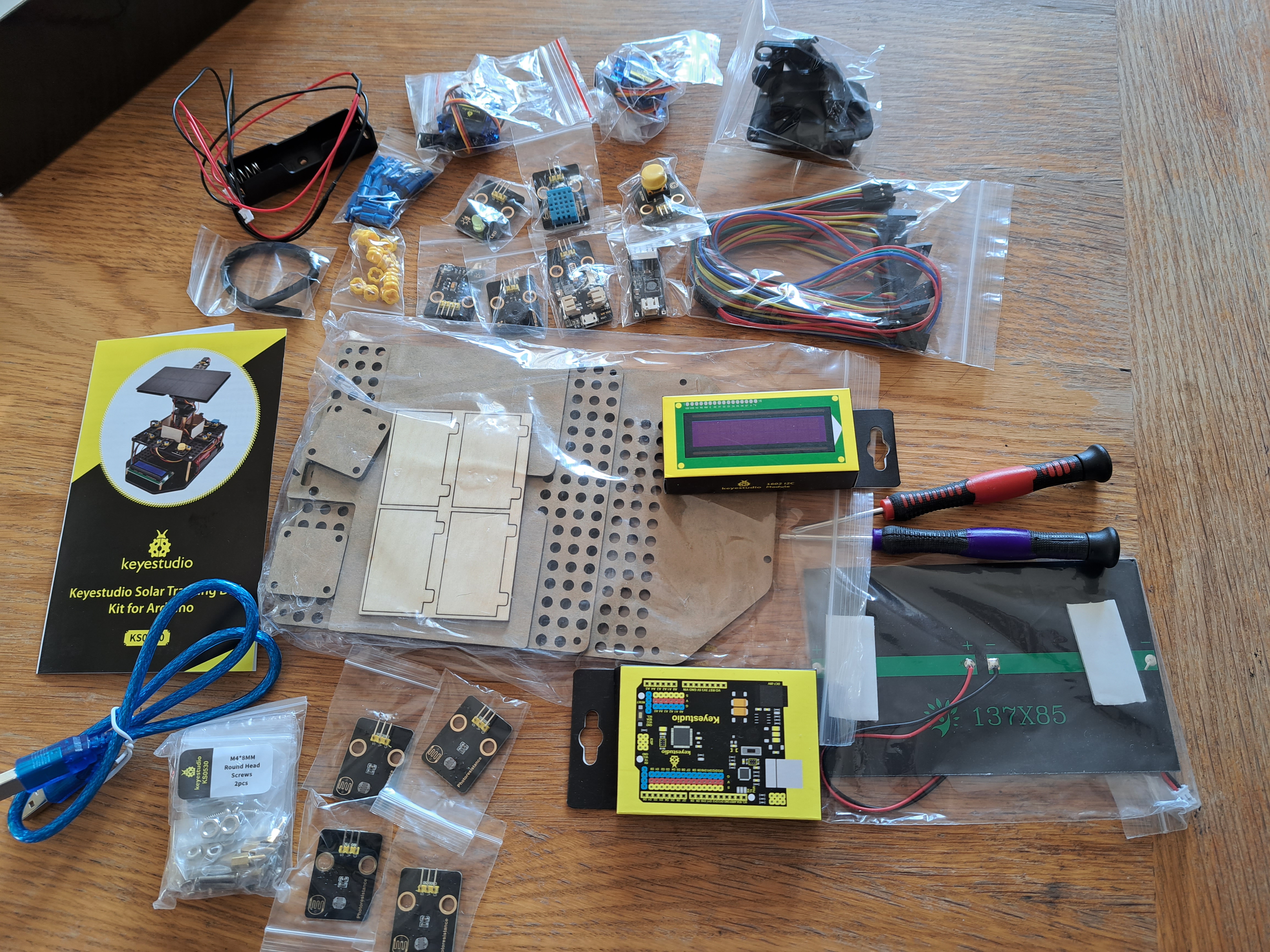
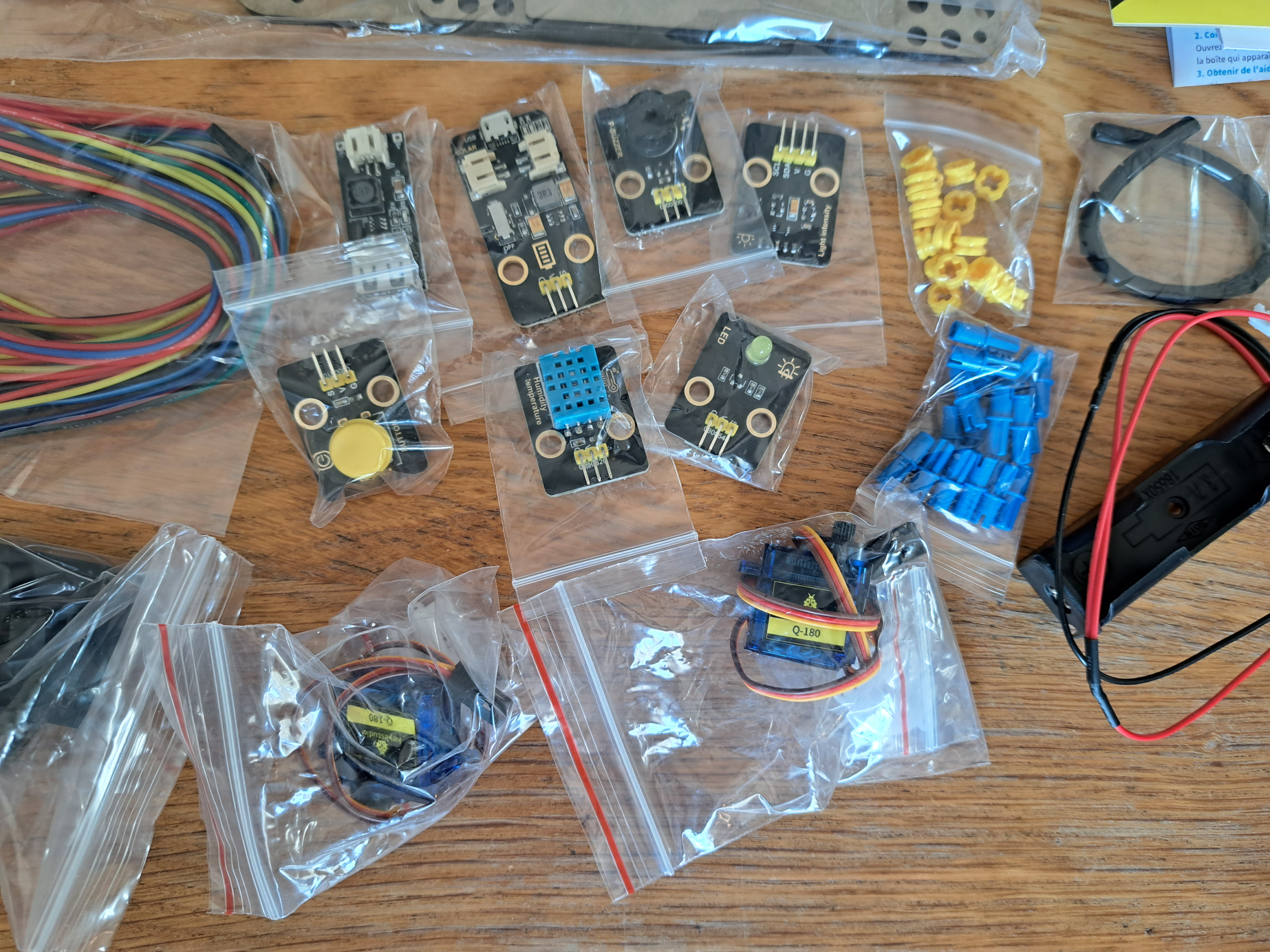
Many sensors (LED, humidity, buzzer, etc) are familiar from other Keyestudio kits. New to this kit is the solar panel as well as a phone charger module - and an interesting new feature: Lego pieces!
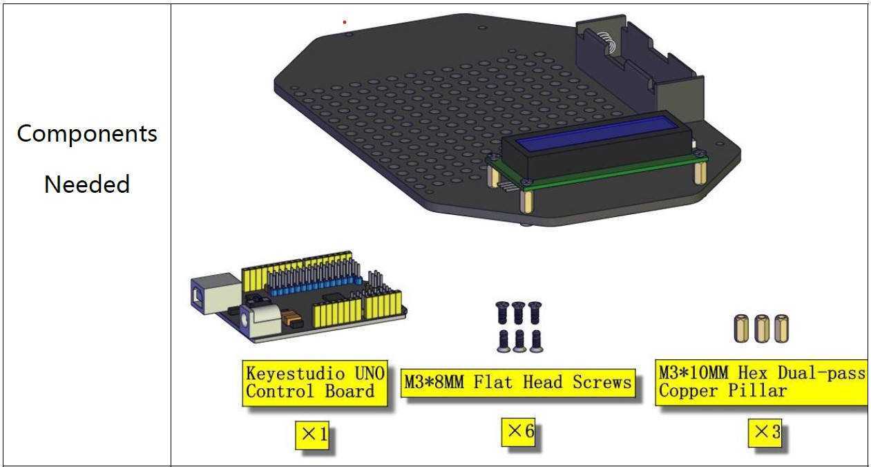
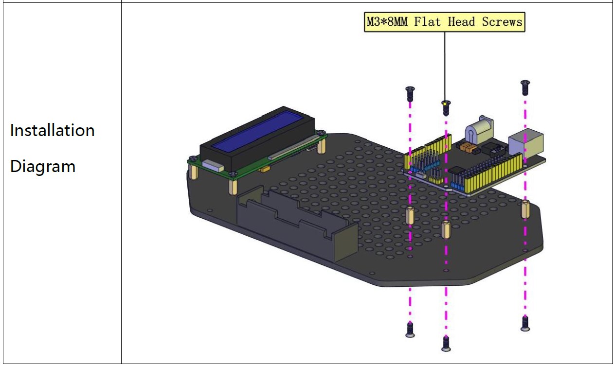
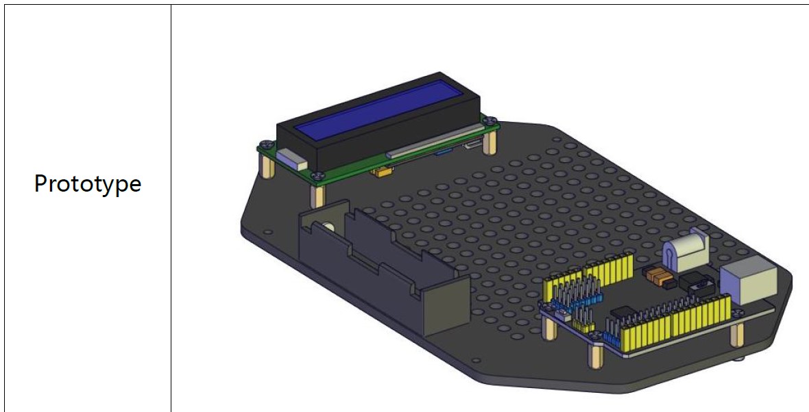
The instruction manual is extremely easy to use. For each step, the required components, installation diagram, and finished prototype are shown (example below). It's quick and easy to work through the assembly. The sentences can occasionally be challenging to understand, however.
Step 1: Building the Device
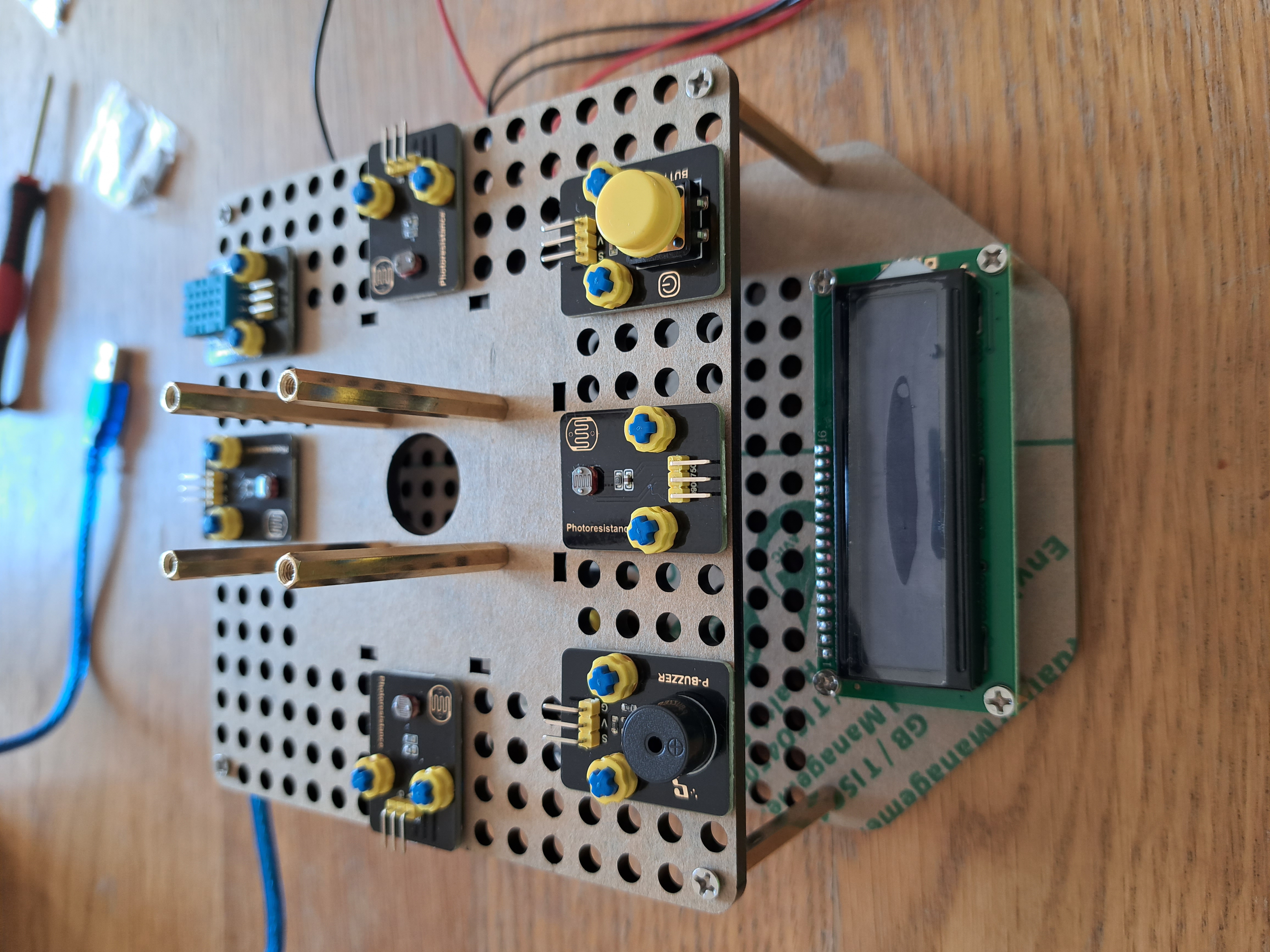
PLATFORM OF SENSORSThe build begins by constructing an acrylic platform of sensors. The platform has 2 layers. The bottom layer has a Keyestudio uno, mobile phone charger, LCD, lithium battery charger, and battery pack. The top layer has 4 photoresistors (1 on each side), buzzer, button, and temperature/humidity sensor.
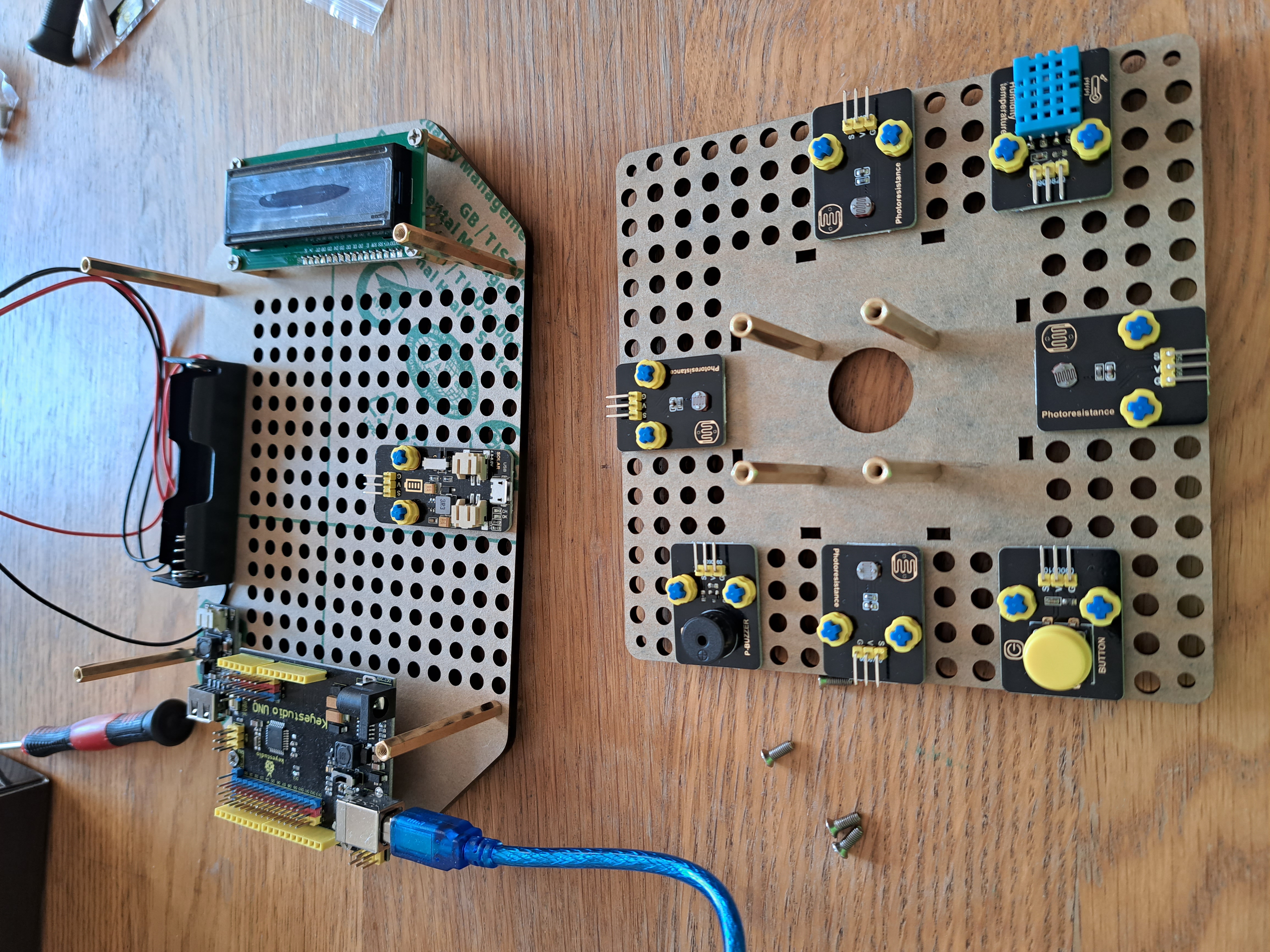
Making the platform is fairly straight-forward using the instruction manual. The only difference I saw was the acrylic boards in the manual are shown with extra holes which didn't exist on my boards. This difference does not affect the build but might confuse some users unfamiliar with similar kits.
A fun feature of the platform is that Lego pieces attach the sensors to the acrylic boards. The ability to integrate Lego into the design opens up a lot of potential extensions!
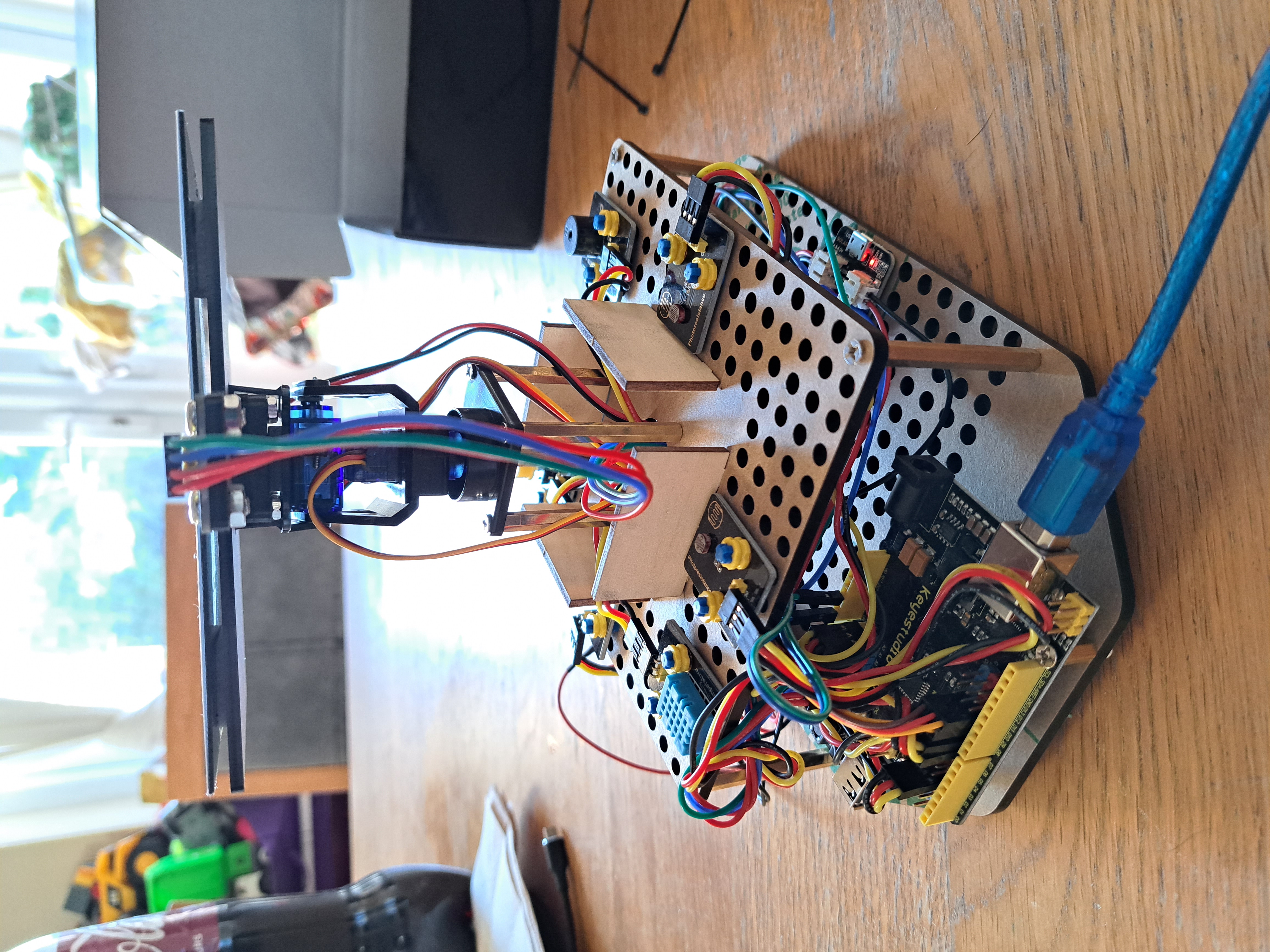
SERVO ASSEMBLY AND SOLAR PANEL
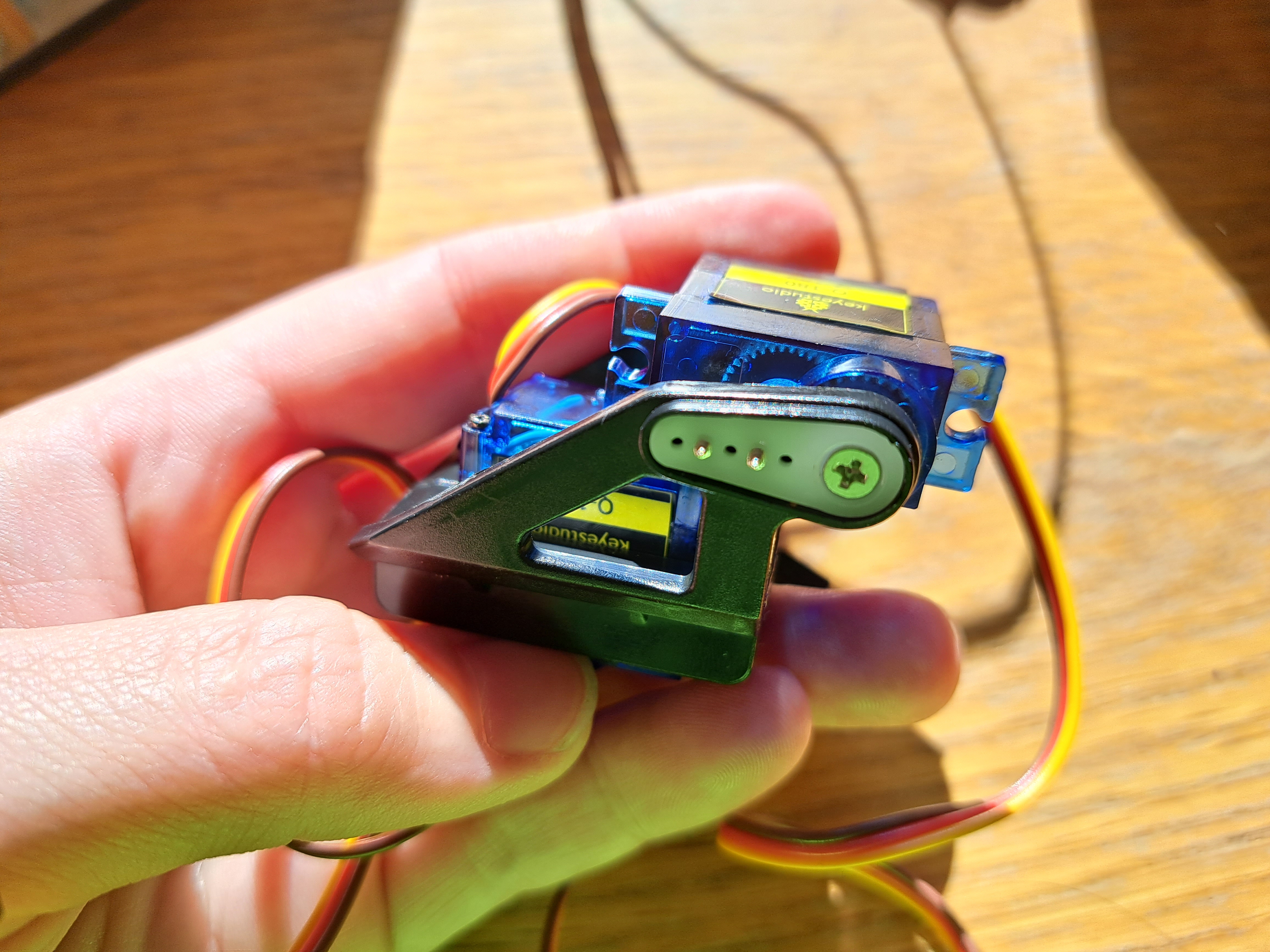
The servo assembly includes 2 servos within a provided support. The first picture shows the bottom servo, which points down to turn left/right. The second picture also includes the top servo, which points to the side and controls up/down position.
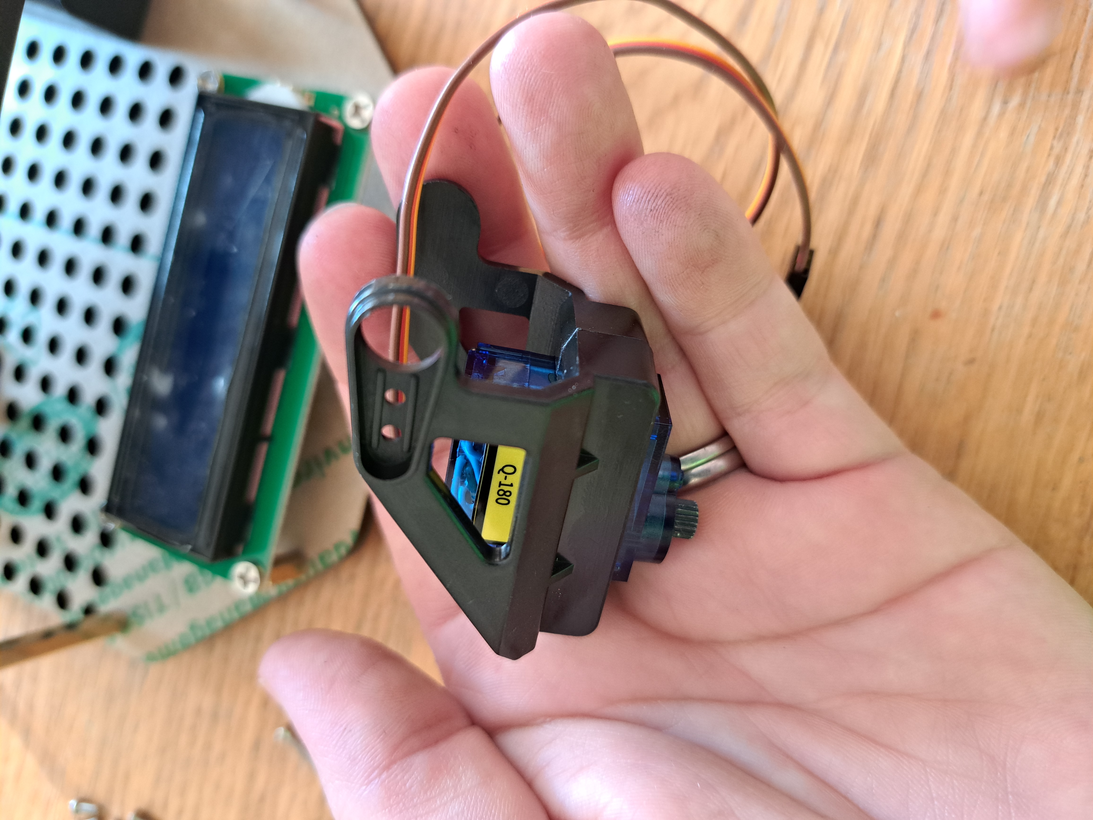
The servo assembly attaches to the sensor plaform via a rotating lower mount, and to the solar panel via a clip-in upper mount.
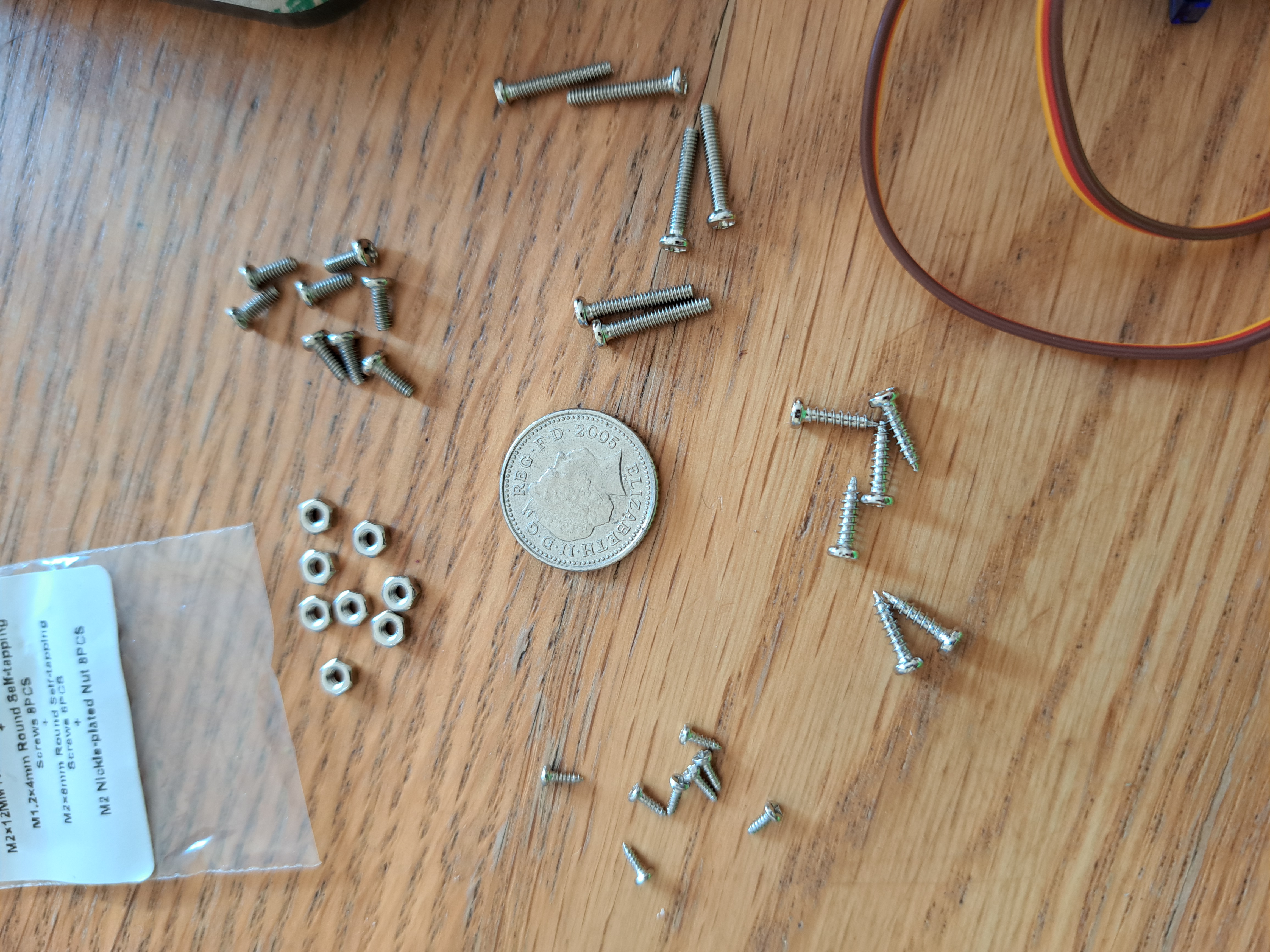
The hardest bit of the build is sorting the bag of mixed, incredibly tiny screws and nuts. Sorting these into piles took me forever and many screws fell on the floor in the meantime. I wanted to take a break in building but felt I had to continue all the way to the end just to avoid needing to re-sort the screws and nuts. Strangely, many screws and nuts haven't been used - so unless they are used during the wiring phase, it seems they are completely unneeded!
Another tricky aspect could be setting the servos' initial angles. The manual provides the arduino code to do this, but there is no explanation of how to wire the servos to the Arduino. A picture of the required wiring would greatly benefit any users not already familiar with Arduinos.
Step 2: Wiring the Device
The manual provides pictures and written descriptions of how to wire each sensor. The explanations are clear - but doing the wiring is difficult. Many wires are in the same small space, and the sensors on the bottom platform are particularly challenging to reach.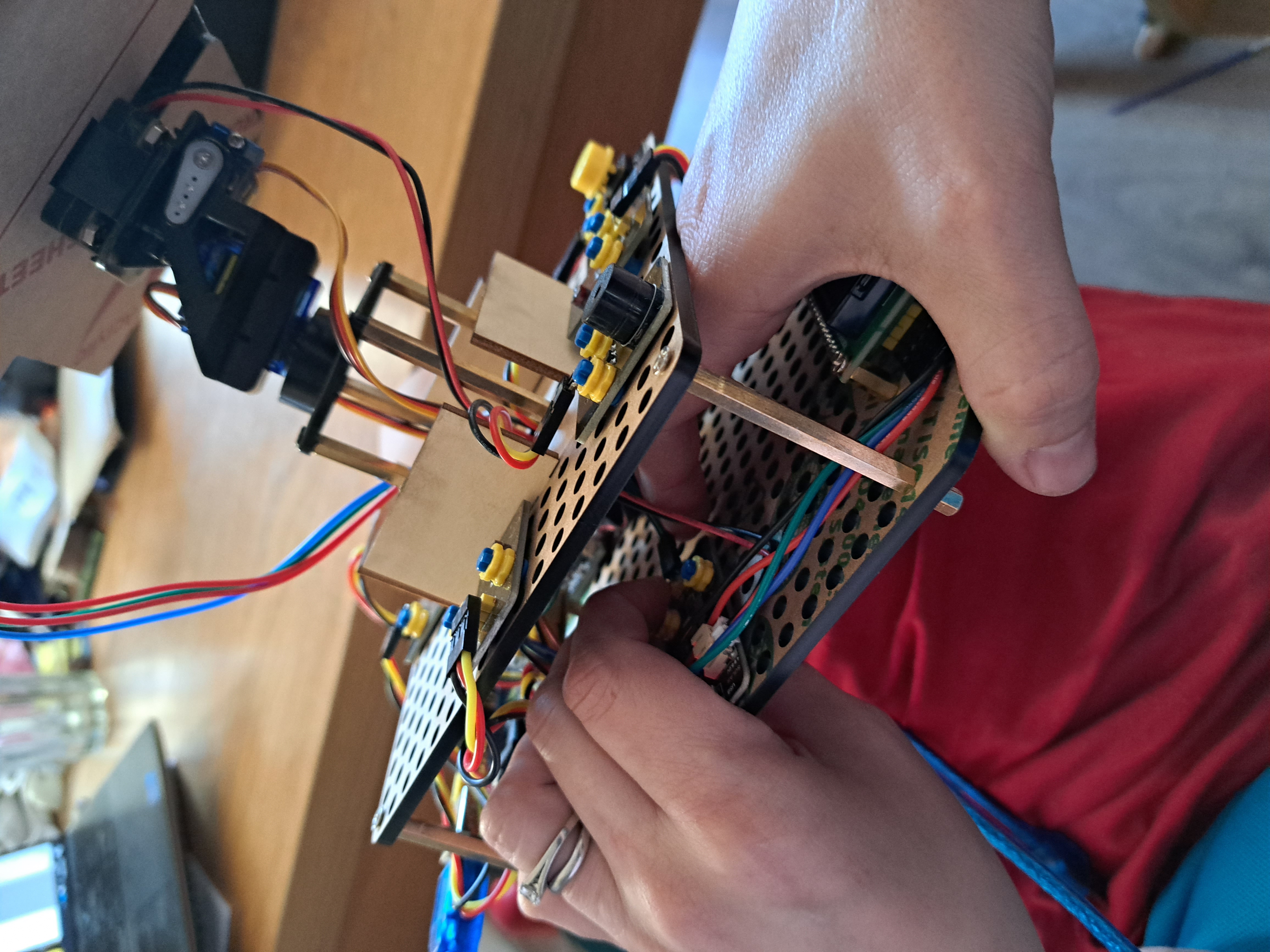
I suggest twisting each set of 3 wires to keep them together,
feeding the top platform wires through the central hole,
and twisting, or even temporarily removing, some components from the platform in order to attach the wires.
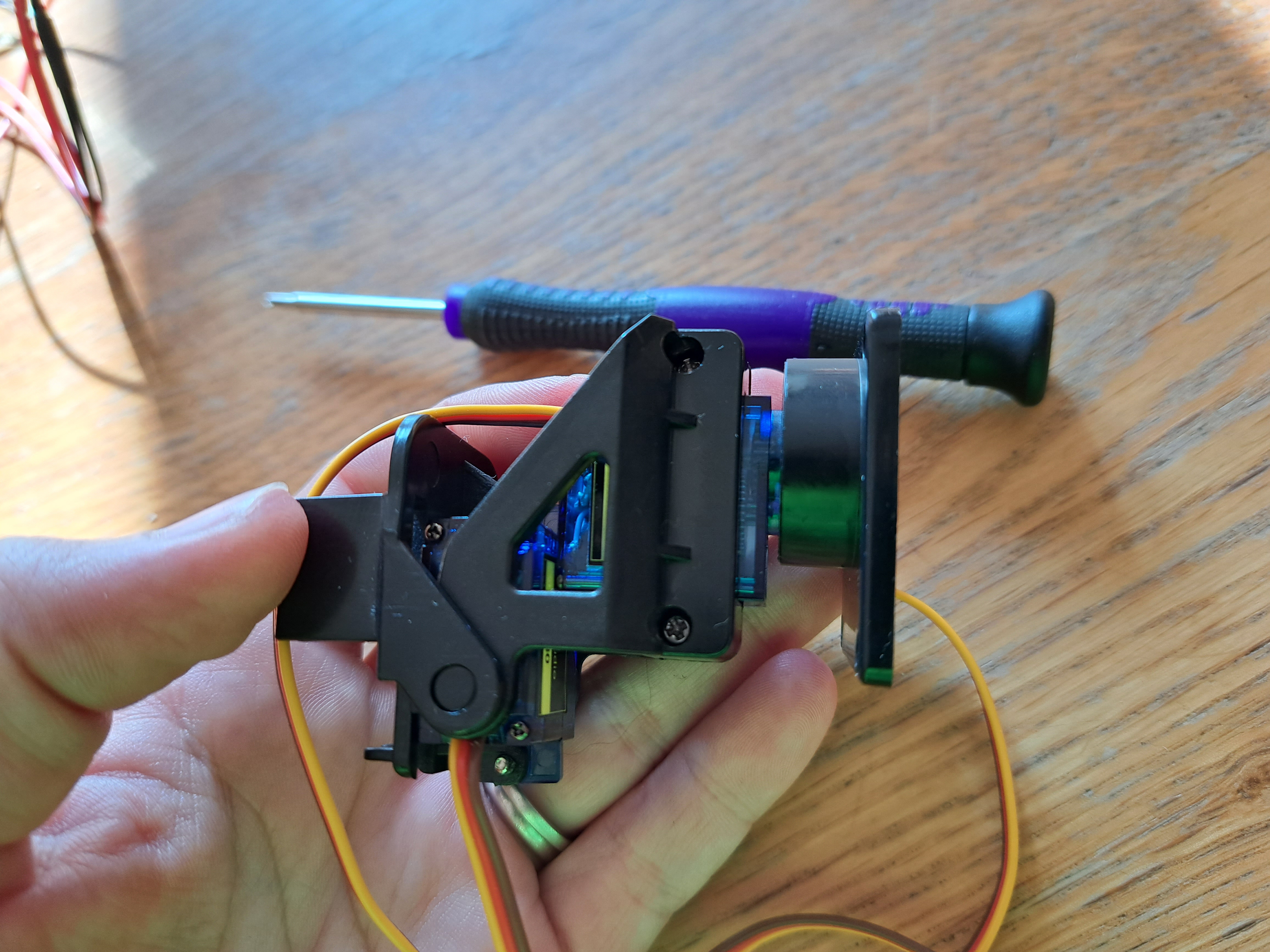
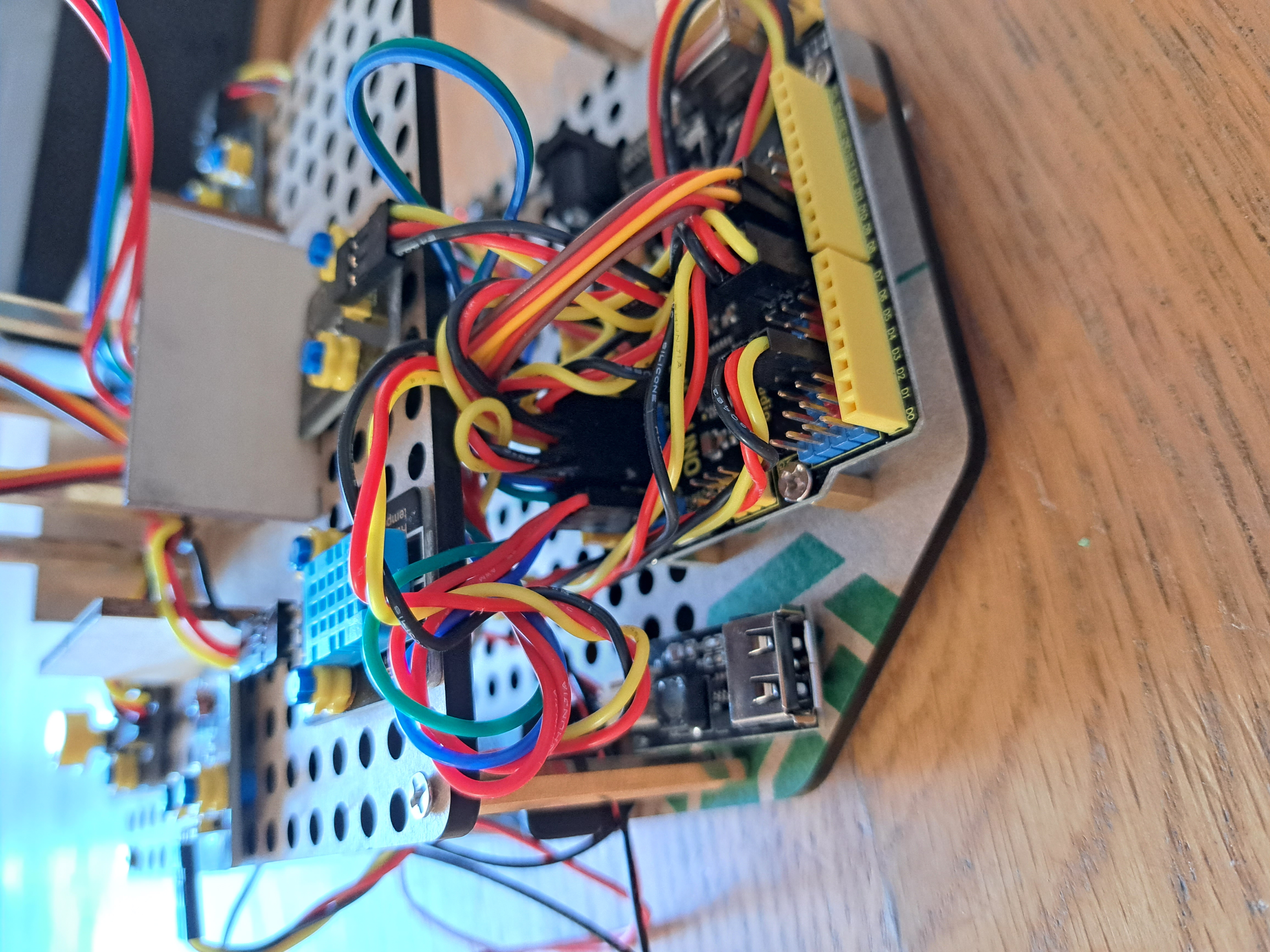
The final wired assembly is shown here. I have suggested other ways to make wiring easier at the end of this review.
Step 3: Using the Device
The device is generally easy to use, even for someone new to electronics/Arduino. Arduino codes are provided free online and run without any errors. The codes are also commented, though sometimes the commenting can be challenging to understand.Sensors are introduced one at a time, with separate codes for each sensor. This gentle introduction is useful for anyone new to electronics. Slightly confusingly, however, Project 1 introduces an LED module which wasn't added to the device previously and doesn't have a connection wire provided. Someone familiar with electronics can easily add and wire the module in, but a beginner would likely struggle.
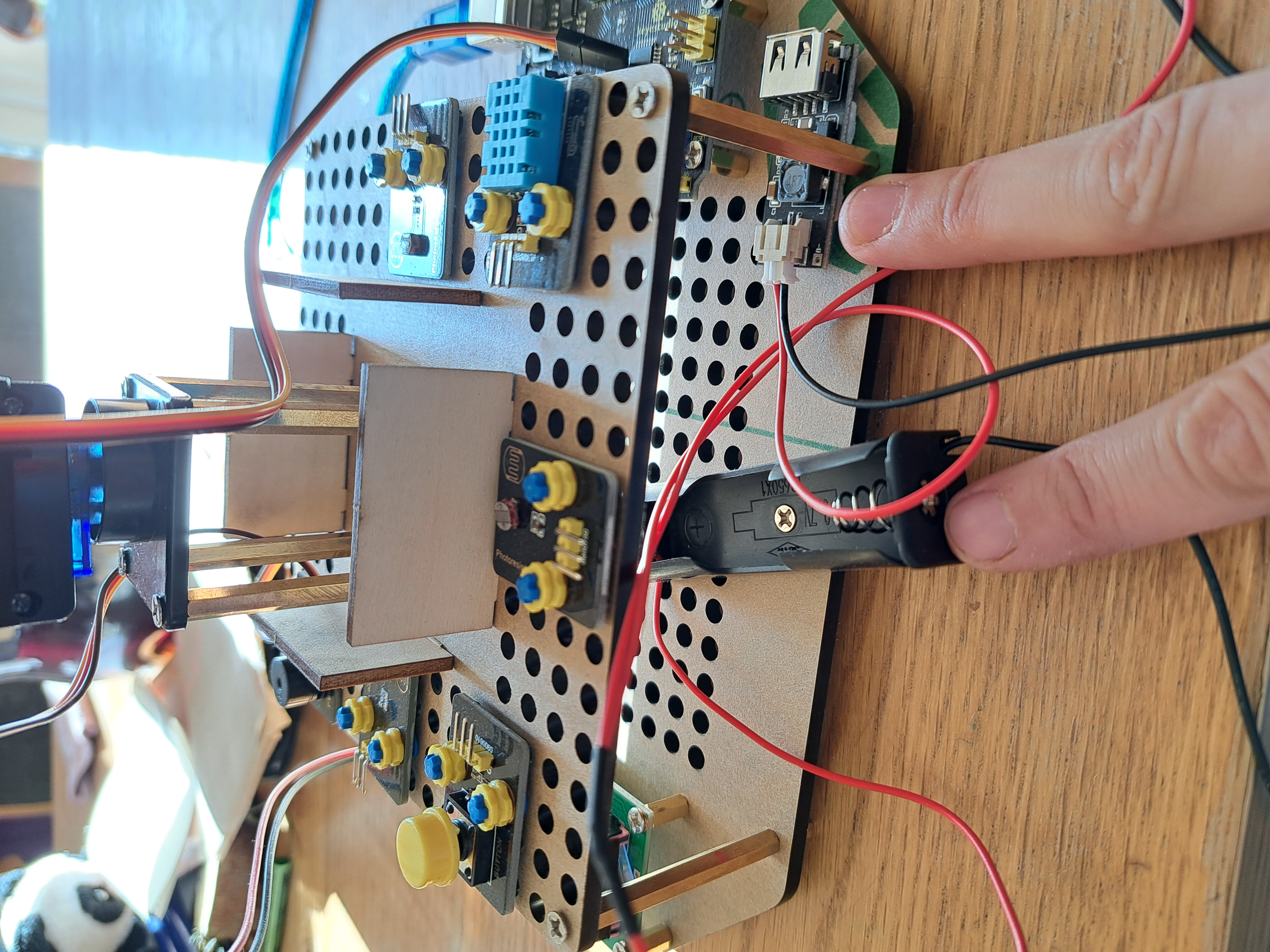
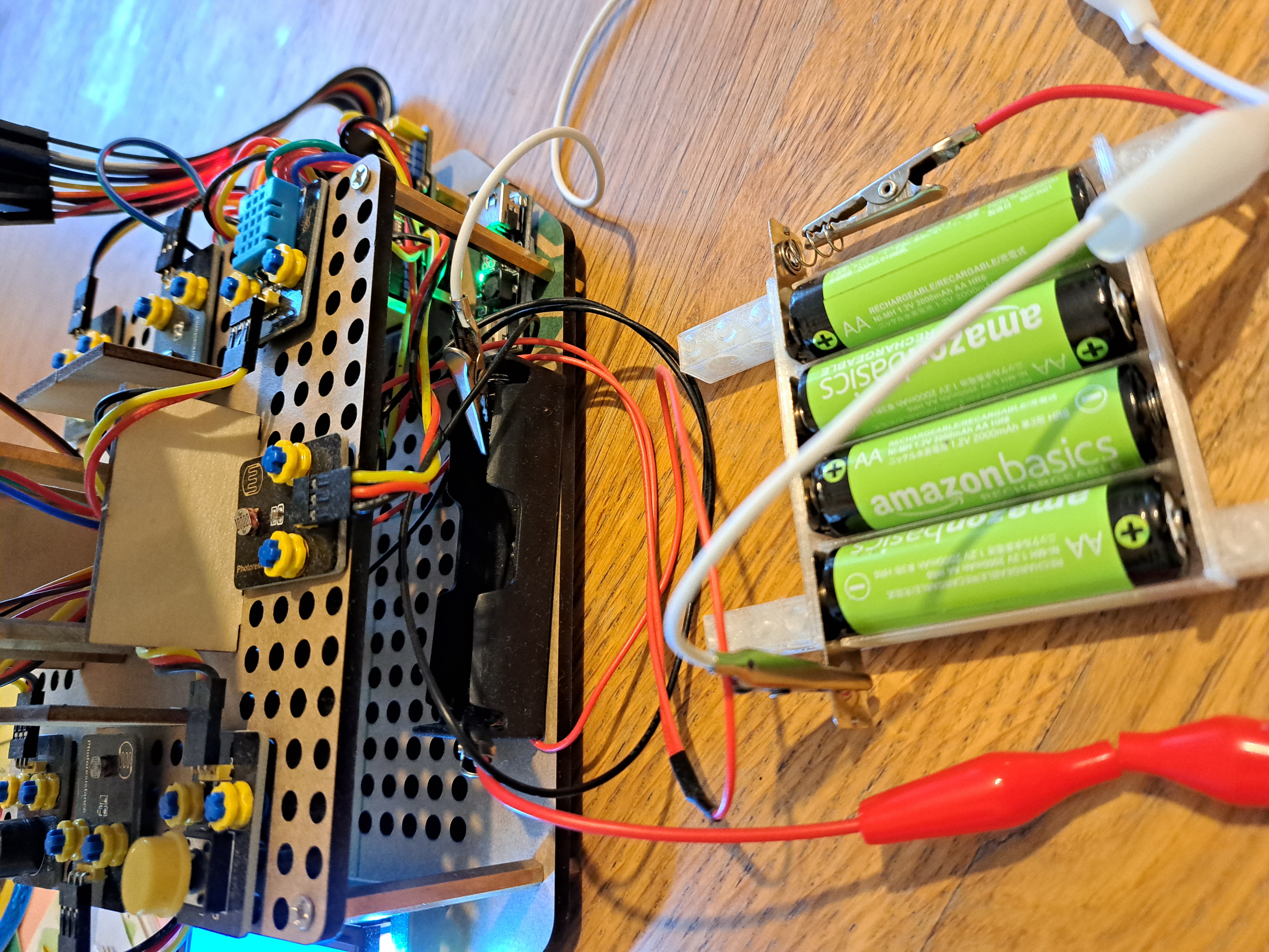
Project 9 introduces the servo sensors. The instructions warn that an external rechargeable lithium battery 18650 is required to power the servo. Otherwise, the Ardiuno may burn out. Providing this warning is great, but the 18650 battery is hard to source. I used 4 AA rechargeable batteries instead and they worked well.
Project 10 introduces the mobile phone charging module. A main feature of this kit is using solar energy to charge a mobile phone. The module has an older USB-A port, however, whereas most current mobile phones have a USB-C port. I briefly looked for an adaptor but gave up and went onto the final project.
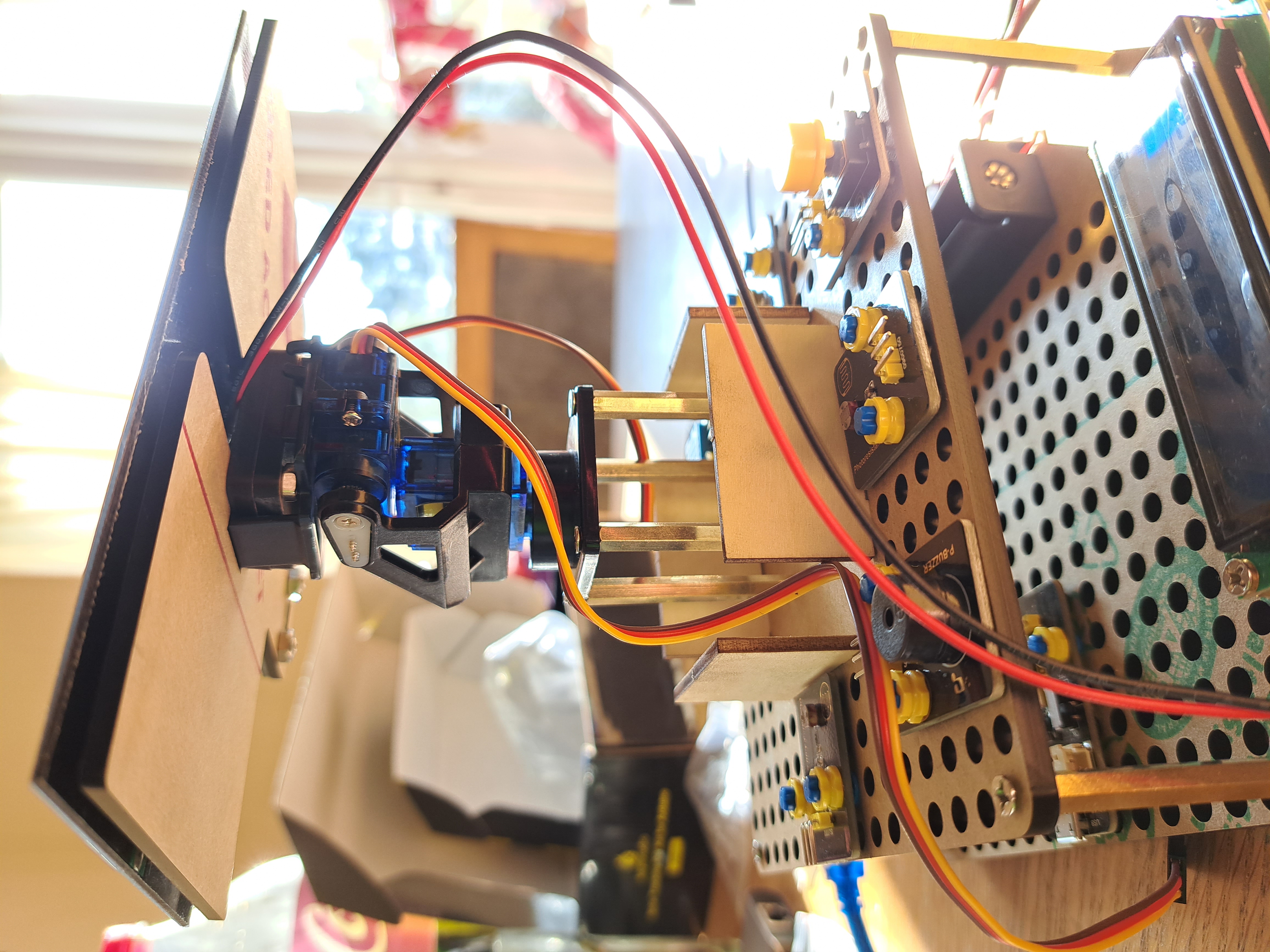
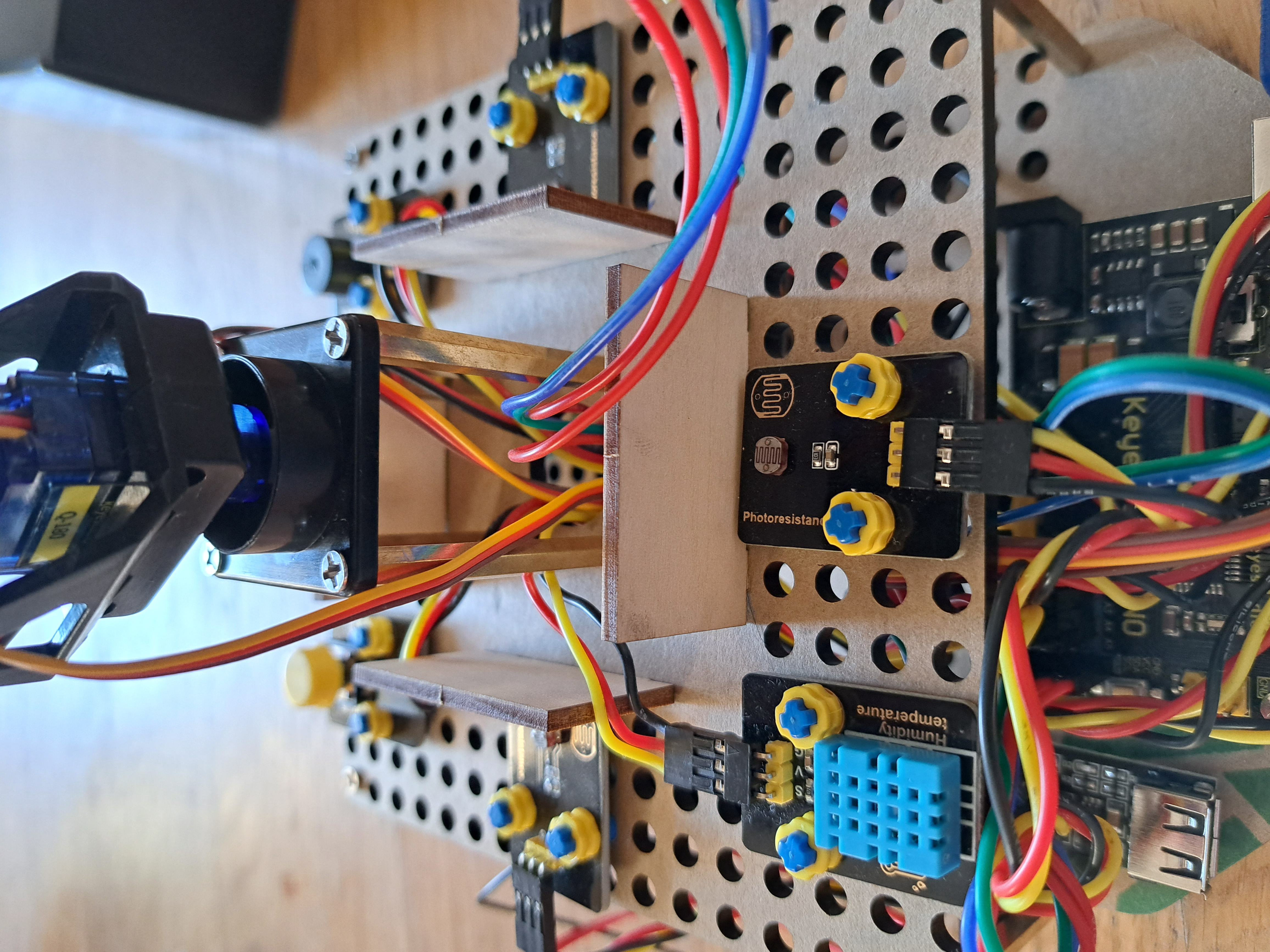
Project 11 combines the sensors and makes the solar panel follow a point light source. I expected the solar panel to move until it was pointing directly at the light source, but this isn't what happens. The device decides the solar panel's left/right position by considering the relative amount of light on the left and right photoresistor sensors. (The 4 photoresistor sensors are on the upper platform with pink pieces of paper under them in the picture below.) The solar panel then turns towards the side with more light. The solar panel stops turning when the relative amount of light on the left and right sensors is the same. Similarly, the device decides the solar panel's up/down position by considering the relative amount of light on the top and bottom photoresistor sensors.
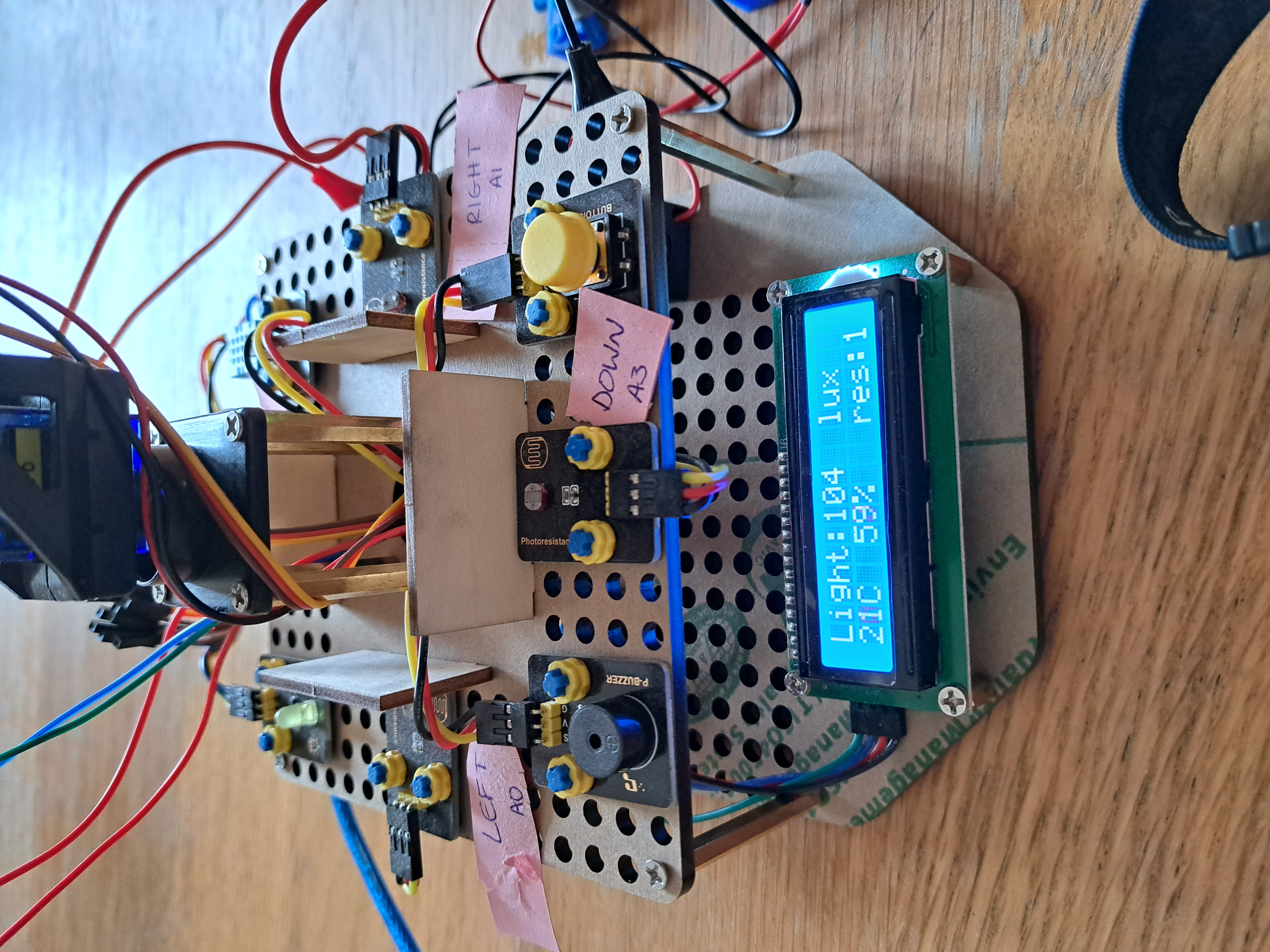
The reason the solar panel does not stop moving pointing directly at the light source is that the 4 photoresistor sensors are stationary on the upper platform. The amount of light each sensor receives is unaffected by the position of the solar panel. Therefore, the solar panel continues turning, attempting to balance the relative amount of light on each pair of sensors, until the solar panel reaches the end of its range (0° or 180° for left/right - and 0° or 90° for up/down).
In summary, the solar panel can successfully follow a point light source (ie, if the light source moves from the left side to the right side, the solar panel will turn to the right). The solar panel will NOT end its motion looking directly at the light source, however (unless the light source happens to be at the end of the turning range anyway). I expected the solar panel to look directly towards the light source so want to stress to anyone thinking of buying the kit that this is NOT what the solar panel will do. Some relatively minor changes to the code would result in the solar panel stopping to look directly at the light source. This is a good extension to the project you may want to try!
A Final Overview!
Things I really liked:-Construction instructions are clear with many pictures.
-Arduino codes are well-commented and run without error.
-Device uses and is compatible with Lego!
-Device is fun to use and offers many opportunities for learning.
-Good opportunity for deep thinking about why solar panel moves as it does (and how to improve the device)!
Things I suggest improving:
-Using 4 AA rechargeable batteries rather than recommended lithium 18650 battery (hard to find).
-Having USB-C port on mobile phone charging unit, rather than older USB-A port (unsupported by newer phones).
-Having solar panel identify and stop pointing directly at light source, rather than turning to end of ranges of left/right and up/down motion.
-Wiring sensors in a different order:
+ wiring bottom sensors before adding top platform of sensors.
+ wiring central sensors before wiring outside sensors.
+ wiring arduino in consecutive rows (ie first sensor in A1, second in A2, third in A3, etc). Otherwise it is easy to accidentally wire the wrong rows.
This is a fun kit, especially if you want to integrate the solar panel or charging module into a Lego construction! More details on how solar panels actually work would have been nice. It would also be better if the solar panel stopping moving looking directly at the light source - it was still fun to make the solar panel follow the light source, however, so I was pleased with the kit.
Other Articles:
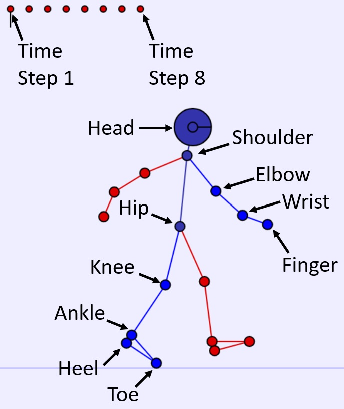
BodyWorks: Kinematics ToolA page with a javascript application where you can set body positions, calculate joint angles and animate human motion. |
|
Three Crystal StructuresA ThreeJS model of three crystal structures |

|
Mars Re-EntryA ThreeJS simulation of Mars re-entry in a spaceship. |

|